Emergency power supply from the inverter WIT is implemented by a separate output that takes over the load within 10 ms of a grid failure. The power available at this output corresponds to the rated power of the inverter, i.e. from 4 kW in the model WIT 4K-HU up to 15 kW in the model WIT 15K-HU, with a two-fold overload capability for 10 seconds. This overload reserve determines whether the heat pump compressor will start after a power outage. Emergency power supply from the inverter WIT however, it requires a well-thought-out division of circuits in the switchboard - otherwise the storage will be discharged on circuits that are not needed in the event of a failure.
How does an inverter backup power supply work? WIT
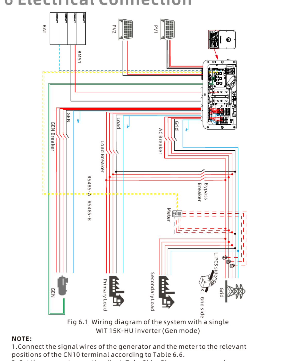
The inverter constantly monitors grid parameters. Upon detecting a voltage drop or exceeding protection settings, it disconnects from the grid and switches to island operation, powering dedicated circuits from the battery and PV system. The manufacturer states a transfer time of no more than 10 ms and a voltage distortion (THDv) of less than 3% with a linear load.
The output parameters for island mode are configurable. In the control menu, you can set the frequency to 50 Hz or 60 Hz and the voltage to 220 V, 230 V, 240 V, 277 V, or 127 V, according to local regulations. For installations in Poland, 230 V and 50 Hz remain appropriate, and the phase-to-phase voltage is 400 V.
Emergency power supply from the inverter WIT It uses the energy stored in the storage facility and the current module production. If the outage lasts longer and it's daytime, the PV system recharges the battery, allowing for backup power to last much longer than the storage capacity alone would suggest. At night, available energy is limited to the battery's capacity, minus the reserve set in the configuration.
Power, overload and starting of motors
The emergency output delivers power equal to the device's rated power, and the allowable overload is twice the rated power for 10 seconds for each model in the series. Output powers and currents are listed below.
| Door Design | Emergency exit power | Max output current |
|---|---|---|
| WIT 4K-HU | 4 kW | 12,2 A |
| WIT 5K-HU | 5 kW | 15,2 A |
| WIT 6K-HU | 6 kW | 18,2 A |
| WIT 8K-HU | 8 kW | 24,2 A |
| WIT 10K-HU | 10 kW | 30,2 A |
| WIT 12K-HU | 12 kW | 36,4 A |
| WIT 15K-HU | 15 kW | 45,5 A |
A two-times overload for 10 seconds covers the startup of most home appliances. A 3 kW heat pump compressor draws several times the rated current for a fraction of a second upon startup, so a 10 kW model with a temporary reserve of up to 20 kW can handle it without any problems. The problem arises with older, direct-start submersible pumps, where the starting current can be six times higher than the rated current.
Select emergency section protection for the maximum output current from the table above. After islanding, the inverter is the source and will not supply a higher current—protection sized for the connection current may never trip.
The limiting factor isn't the inverter itself, but the battery. A module with a permissible current of 140 A at a voltage of 51,2 V will output approximately 7,2 kW continuously. Connecting such a storage device to a 15 kW inverter doesn't provide 15 kW of emergency output—the island's actual power output is determined by the weaker component in the system.
Which circuits should be connected to the emergency power supply from the inverter? WIT
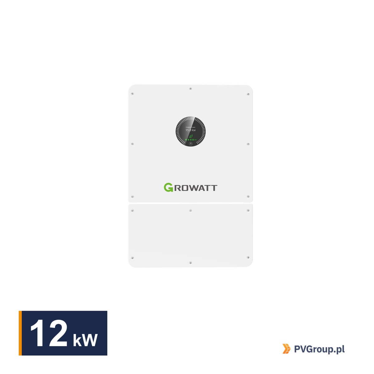
Emergency power supply from the inverter WIT covers a separate section of the installation, not the entire house. The division of circuits is done at the distribution board design stage, and in practice, it determines customer satisfaction with the system.
It is worth directing the following to the emergency exit:
- basic lighting in the kitchen, bathroom and hallways,
- fridge and freezer,
- a boiler or heat pump with circulation pumps, if a failure in winter is not to freeze the installation,
- router, monitoring, automation controllers and entrance gate,
- water pump in houses with their own intake,
- one or two sockets in each utility room.
High-drain circuits that are not essential during an outage should be left outside the emergency exit: the car charger, sauna, induction cooktop, air conditioning, and sockets in the garage and workshop. Each of these can empty a storage unit that was supposed to last overnight in just a few minutes. Control logic for receivers via dry contacts—using the example of devices. off-grid Growatt — we showed in the text about dry contact control.
Circuit separation requires a separate section of the switchboard, powered by an emergency exit, with its own differential and overcurrent protection. Temporary solutions, in which the entire switchboard is isolated, result in the protection tripping at the first significant load.
Grounding and neutral point in island operation
Emergency power supply from the inverter WIT This changes the neutral point reference. During grid parallel operation, the installation's neutral point is referenced to the operator's grid. After islanding, this reference disappears, and the installation requires its own N-PE connection for the differential protection to function properly. Hybrid inverters implement this via an internal relay that shorts the N to PE in island mode, but the connection method on the distribution board side should be checked in the documentation for the specific model.
Neglecting this issue is one of the most common mistakes in initial backup installations. This manifests itself in island mode, where the differential circuit breaker fails to respond to ground faults, or, conversely, trips every time the load is started. The installation is then formally operational, but the protection does not protect the user. Coordinating grounding and surge protection for the entire installation is described in the article on lightning protection for PV systems.
The inverter operates in 3P3W+PE and 3P4W+PE systems at 220/230 V LN and 380/400 V LL. The choice of system affects the neutral conductor routing to the emergency section and must be determined before the switchboard is installed.
Operating modes and emergency power supply from the inverter WIT
The inverter has several operating modes, and their settings determine how much energy will be stored in the event of a power outage. WIT uses exactly this reserve, so the mode configuration translates directly into the backup time.
- Load First — Priority is given to powering loads from the PV system and batteries, with any surplus going to the grid if export limitation is disabled. This mode requires a meter or three current transformers.
- Grid First — the energy from the modules powers the receivers, the surplus goes to the grid, and only the remaining part charges the storage.
- Battery First — the modules charge the battery to a preset charge threshold and only then power the loads. When production is insufficient, the inverter draws power from the grid to recharge the storage.
- Idle — the battery is neither charged nor discharged, and the home balance is based on the modules and the network.
In regions with frequent grid outages, it makes sense to set battery priority mode and increase the SOC reserve. This allows the storage to maintain a higher charge level at the expense of some savings on self-consumption. In regions with a stable grid, the opposite is true—a lower reserve means more energy is used immediately.
The inverter enters standby mode when the PV voltage exceeds 150 V, and starts at a voltage of at least 165 V. This is important when starting the system in the morning after an overnight outage, when the storage unit is empty and the modules are just starting up. We described the scheduling method for the dynamic tariff, including the SOC reserve, in the article on Smart Scheduling mode —the higher the reserve, the shorter the storage unit's daily self-consumption time, so it's worth agreeing on a numerical value with the customer.
How long will the emergency power supply from the inverter actually last? WIT
Backup time is calculated simply: the usable capacity of the storage unit is divided by the power drawn by the emergency section. Below are typical variants for a storage unit with a usable capacity of 13,3 kWh, assuming that the PV installation does not produce.
| Emergency section load | What does it usually include? | Backup time |
|---|---|---|
| 0,5 kW | refrigerator, router, LED lighting, automation | about 26 hours |
| 1 kW | as above plus circulation pumps and boiler | about 13 hours |
| 2 kW | as above and heat pump in limited mode | approximately 6,5 hour |
| 4 kW | heat pump in full operation in winter | approximately 3 hour |
These values are approximate, as actual consumption varies over time, and the inverter itself consumes some energy. However, they illustrate the scale: the difference between an emergency section covering only critical circuits and one that supports heating is between a day and three hours.
During the day, the bill looks different. Emergency power from an inverter WIT It also utilizes the current production of modules, so in sunny weather, the storage facility can recharge during an outage. With a 10 kWp installation and an emergency section consumption of 1 kW, the system can operate indefinitely as long as the day lasts. In winter, with cloud cover and production of several hundred watts, this mechanism is practically ineffective.
It's worth providing the customer with two numbers: the nighttime backup time and the information that the PV system extends it during the day. A single number will always be misleading.
From the installer's practice
Test the backup power from the inverter WIT upon acceptance of the installation. Turn off the main fuse and check what's actually working, how much the house is drawing, and whether the heat pump is starting. A five-minute test in front of the customer saves you from later discussions about why the backup didn't work as the customer expected.
Establish a written SOC reserve with the client. A client who sees a storage unit charged to 30% on a sunny day will call with a vengeance. If they know in advance that 30% is a deliberate reserve for emergencies, the conversation is different.
In practice, we often encounter situations where the emergency section is designed too broadly. A house connected entirely to the emergency exit discharges the storage within an hour because the boiler, kitchen, and air conditioning are running. A narrower section with truly necessary circuits provides several hours of backup power.
Check the behavior of sensitive devices. A switching time of less than 10 ms is sufficient for most equipment, but some switching power supplies and older boilers with their own automation react with a reset. A field test is the only reliable way to verify this.
Documentation for designing the emergency section
The emergency exit connection diagrams and island operation parameters are described in the operating instructions that we provide on our websites:
- Instruction WIT 4-15K — system diagrams, operating modes, off-grid operating parameter settings.
- Instruction WIT 17-25K — description of the function of starting the system without the presence of a network.
- Quick Installation Guide — Polish version with a table of wire cross-sections.
When designing a switchboard, it is worth having the diagram from the manual open next to the electrical drawing - the distribution of priority and secondary loads is clearly shown there.
FAQ
Is the backup power from the inverter WIT works without batteries?
No. Island operation requires energy storage because the modules alone cannot maintain stable voltage under varying loads and cloud cover. An inverter without a battery operates solely in grid-connected mode.
How long will the house last on emergency power?
This depends on the usable storage capacity and the power of the emergency section. At 13,3 kWh useful and with a load of 1 kW, the backup time is up to several hours, with a load of 4 kW it is reduced to about three. During the day, the PV installation extends this time.
Do you need to rebuild the switchboard?
Typically, yes. An emergency section requires separate circuits, its own protection, and proper N-PE connection in island mode. In existing homes, this means expanding the existing distribution board or installing an additional one.
Will the emergency exit handle a single phase load?
The inverter is a three-phase device, and the emergency output is also three-phase. Single-phase loads are distributed between the phases at the design stage to ensure that the permissible asymmetry specified by the manufacturer in the model documentation is not exceeded.
Backup Startup Checklist
- Establish a list of circuits that will be served by the inverter backup power supply. WIT, and calculate their total power.
- Compare this sum with the emergency output power of the selected model and the battery discharge current.
- Design a separate section of the switchboard with its own protection.
- Disconnect the N-PE connection for island operation according to the device documentation.
- Set the charge state reserve and operating mode according to the frequency of failures in your area.
- Perform the test by disabling the main protection and record the result in the acceptance protocol.
12 kW models, for example WIT 12K-HU, provide a reserve of island power for a home with a heat pump. A complete list of available units is available at series inverter department WIT, and detailed wiring diagrams for the emergency section can be found in the instructions in manufacturer's download center.