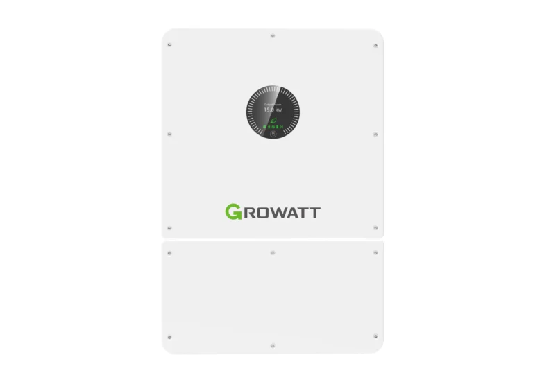
Expansion of the energy storage facility HOPE involves adding subsequent modules in parallel - up to 48 units in the 14.3L-A1, 14.3L-R1 and 5.0L-P1 variants and up to 12 units in the 5.5L-A1 version. Expansion of the energy storage HOPE It simultaneously increases capacity and allowable current, but the real limit is usually set not by the battery, but by the inverter. Sensible planning of the stages requires three decisions right from the initial installation: location, wire cross-section, and module variant selection. Below, we describe how to manage this so that the second phase doesn't mean reworking the first.
Expansion of the energy storage facility HOPE — parallel connection limits
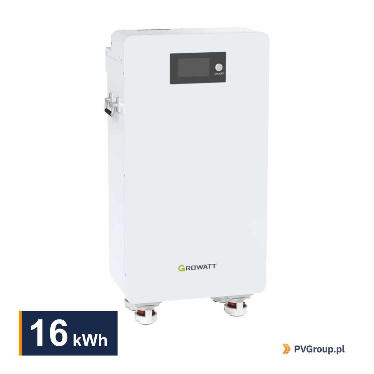
The manufacturer specifies the maximum number of modules in a system separately for each variant. This translates into very different capacity levels.
| Door Design | Module capacity | Max number of modules | Module current |
|---|---|---|---|
| HOPE 14.3L-A1 | 14,3 kWh | 48 | 140 A |
| HOPE 14.3L-R1 | 14,3 kWh | 48 | 220 A |
| HOPE 16.0LM-A1 | 16,0 kWh | 48 | not specified in the card |
| HOPE 5.0L-P1 | 5,12 kWh | 48 | 100 A |
| HOPE 5.5L-A1 | 5,5 kWh | 12 | 100 A |
The maximum capacity of the system is the product of the module capacity and the permissible number of pieces - for modules 14,3 kWh gives 686,4 kWh, and for 16 kWh up to 768 kWhYou can download catalog cards of all variants from manufacturer's download center.
The numbers in the last column are more important for expansion than capacity. The current is added together with the number of modules, so three 14.3L-A1 modules theoretically give 420 A. The inverter series WIT The 4-15K-HU accepts 110A to 290A depending on the model, while the 17-25kW units accept up to 420A. The inverter, not the battery, sets the ceiling. This parallel architecture is a feature of low-voltage systems—see the text for a comparison with HV towers. high voltage or low voltage inverter.
Expansion of the energy storage facility HOPE — what to plan at the start
Decisions made during the first module determine the costs of the second stage. Three of these decisions are most important.
Space. The 14.3L-A1 modules are 440 mm wide and 812 mm high when wall-mounted, while the 16.0LM-A1 variant is a free-standing unit. Leaving a free space next to the first module costs nothing, and not having one means running cables to the other wall or another room later.
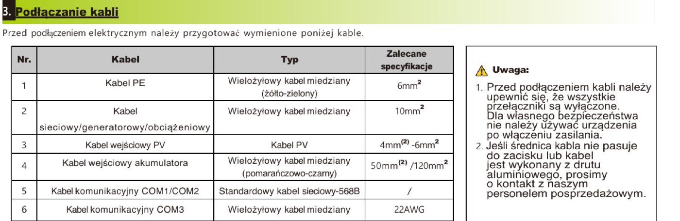
Wire cross-section. A route selected for a single 140A module will not support three. At 51,2V, currents are high, and the voltage drop across a too-thin wire drains some power and heats the connections. The cable is selected for the target number of modules, even if the customer starts with just one.
Choosing a variant. Modules of different types are not combined in a single system. Choosing between the 14.3L-A1 and 14.3L-R1 is therefore a choice for the entire lifespan, not just the first stage. The R1 variant with a current of 220 A offers more flexibility with large inverters, while the A1 variant with a 93% depth of discharge offers slightly more usable energy.
Communication and addressing during expansion
The modules communicate via CAN or RS485. In a multi-module system, one module acts as the master, exchanging data with the inverter, while the others report to it. Each module must have a unique address, set using a switch on the housing.
The most common errors in this area include a duplicate address, missing termination on the last module in the chain, and a communication cable running parallel to the power cables. This symptom can be misleading: the system displays lower capacity than installed, or loses communication only under heavier load, when interference increases.
After each upgrade, the configuration must also be updated on the inverter side—the number of modules and capacity are parameters entered manually. Skipping this step leads to incorrect state-of-charge calculations and premature charging termination.
Connecting a module to a working system
Expansion of the energy storage facility HOPE After a year or two, the difference between a new and a used module must be taken into account. A factory-new module arrives partially charged, while a working set has a different state of charge and a different cycle history.
The practical order looks like this:
- Turn off the system and disconnect the batteries from the inverter according to the manufacturer's procedure.
- Check the voltage of each module separately with a meter, including the new one.
- Bring the modules to approximately the same voltage before paralleling them.
- Make power connections with equal length cables for each module.
- Set addresses and termination in the communication path.
- Update the capacity configuration in the inverter and perform a full check cycle.
The equal length of the wires between the modules and the common point is not a cosmetic detail. Differences in resistance cause uneven current distribution, causing one module to work harder than the others and lose capacity more quickly.
When expansion no longer makes sense
Adding additional modules has diminishing returns once the storage ceases to be a bottleneck. If the battery doesn't discharge below half its capacity in a typical day anyway, another module won't increase self-consumption—it will only increase the reserve in the event of a grid failure, which can be a goal in itself, but it needs to be stated explicitly.
The second signal indicates that the inverter's current limit has been reached. When the sum of the module currents exceeds the device's allowable value, the excess current remains unused. Expanding the energy storage HOPE it only makes sense to replace the inverter with a more powerful one, which changes the economic calculation of the entire project.
The third issue concerns the age of the existing modules. Adding a new unit to a system that has been in operation for five years means a system where the older modules are limiting the overall system. At this age, it's more prudent to consider a separate system or replacing the entire system.
Staging: from one module to the final system
The most common scenario in single-family homes looks like this: the first year without a storage unit or with a single module, the second stage after the first heating season, when the customer already knows their consumption profile. HOPE in this arrangement it is cheap, provided that the first installation was made with the second one in mind.
A good benchmark is measured consumption, not declared. After a year of operation, the monitoring system shows how much energy the house draws after sunset and how often the storage capacity drops to the minimum threshold. If the battery ends the day empty every day, a second module makes sense. If it rarely drops below half capacity, the expansion won't pay for itself through self-consumption.
When planning the next steps, also consider changes to the building. Replacing a gas boiler with a heat pump doubles winter electricity consumption, and installing a car charger can increase it even further. Expanding the energy storage system HOPE planned together with such investments is cheaper than two separate team trips.
The final element is the warranty. Modules purchased later have their own, later warranty period, so the system's coverage ends immediately. This is generally an advantage for the customer, but it's worth clarifying this when submitting the documentation.
After adding modules, also recalculate the charging schedule. The larger capacity of the dynamic tariff means that the cheap hours window must be enough to charge two modules instead of one. At 140A per module, this is usually sufficient, but the hours and SOC thresholds must be updated manually. We show how to do this in the article about mode Growatt Smart SchedulingThis is how the planned expansion of the energy storage facility is HOPE increases self-consumption from the first day, and not only after the next service visit.
When will the energy storage be expanded? HOPE pays off financially
The second module makes sense when the first one actually ends the day empty. Monitoring shows this directly: if the charge level regularly drops to the set minimum threshold beforewitem, the storage is the bottleneck and each additional kilowatt-hour is used daily. If the battery rarely drops below half capacity, expanding the energy storage HOPE will not increase self-consumption - it will only increase the reserve in the event of a network failure.
Seasonality plays a significant role here. Storage chosen in summer appears to be sufficient, as production covers consumption until late in the day. The same system in winter, with a heat pump and short daylight hours, discharges in a few hours. Therefore, it's best to base cost-effectiveness assessments on data from January and February, not June.
Warranty considerations are also key when planning subsequent stages. Modules purchased after two years have their own, later coverage period, so the system's warranty doesn't expire at the same time. On the other hand, cells from different production batches age slightly differently, and in a parallel system, the weaker module determines the overall performance during deep discharge. If the upgrade is a certainty and will occur within a year, it may be cheaper to purchase the entire set at once.
From the installer's practice
Record the model and software version in the as-built documentation. Two years later, no one remembers whether the A1 or R1 variant was installed, and ordering the wrong module blocks expansion for weeks.
Buy modules from the same batch whenever possible. Cells from different production batches age slightly differently. If you plan to expand in the near term, it's better to buy a complete set at once, even if some parts have to wait for assembly.
In practice, we often encounter expansions blocked by lack of space. The first module was installed in the corner of the boiler room, right next to the boiler, and the second module no longer fit while maintaining the clearances required for convection cooling. Planning the wall for two modules from the outset solves this problem at no cost.
Check the room temperature before expanding. A larger warehouse dissipates more heat at full load, and convection-cooled modules require free airflow. A tight, enclosed bay becomes problematic with two modules, although it was sufficient for one.
Documentation useful for expansion
Expansion of the energy storage facility HOPE is based on the limits from the catalog cards of the modules that we provide:
- HOPE 14.3L-A1 — 48 module limit and current parameters.
- HOPE 16.0LM-A1 — free-standing variant for large systems.
- HOPE 5.0L-P1 — module 5 kWh for single-phase installations.
Planning how to expand the energy storage HOPE What is it supposed to look like in a few years? Include a catalog card in the as-built documentation. Subsequent service teams typically don't have access to the order history, and the document revision number allows you to reconstruct exactly what was installed.
FAQ
How many modules HOPE can they be connected in parallel?
The 14.3L-A1, 14.3L-R1, 16.0LM-A1, and 5.0L-P1 variants allow up to 48 modules. The 5.5L-A1 version is limited to 12 modules.
Can I combine modules of different types?
No. A parallel system is built with modules of the same model. Different variants have different currents, depths of discharge, and protection thresholds, which leads to uneven operation.
What limits expansion in practice?
The most common permissible inverter current. Series WIT The 4-15K-HU accepts from 110 A to 290 A, and the 17-25 kW units up to 420 A. After reaching this value, subsequent modules only increase the capacity, not the power.
Does the expansion require changes to the inverter configuration?
Yes. The number of modules and capacity are entered in the device settings. Without an update, the inverter incorrectly calculates the state of charge.
Expansion Checklist
- Check the model and version of the installed modules and the availability of the same variant.
- Compare the total current of the target system with the inverter limit.
- Verify space, cooling clearances and structural load-bearing capacity.
- Check that the existing wiring will handle the target current.
- Equalize the module voltages before parallel connection.
- Set addresses, termination and update configuration in the inverter.
- Perform a complete inspection cycle and record the result in your records.
For the expansion of large systems, the most frequently chosen module 16 kWh in a free-standing version, and with series inverters WIT they are ready to work 15 sets kWh with wiringThe team will select the expansion stages for a specific inverter. PVGroup.pl.