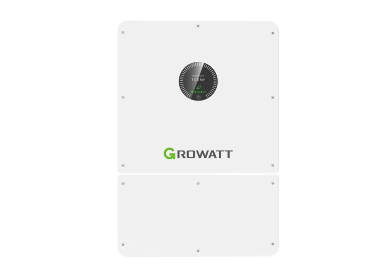
Connecting the inverter WIT to the network requires determining three things: the grid layout, protection settings consistent with the operator's requirements, and a method of limiting the power fed into the grid. Series inverters WIT-HU operate in 3P3W+PE and 3P4W+PE systems, with a voltage of 220/230 V between phase and neutral and 380/400 V between phases, with a tolerance of -15% to +10%. Correct connection of the inverter WIT to the grid also includes the installation of a bidirectional meter or three current transformers, without which neither Load First mode nor export limitation will work. We discuss each of these elements below.
Connecting the inverter WIT to the network - systems and parameters
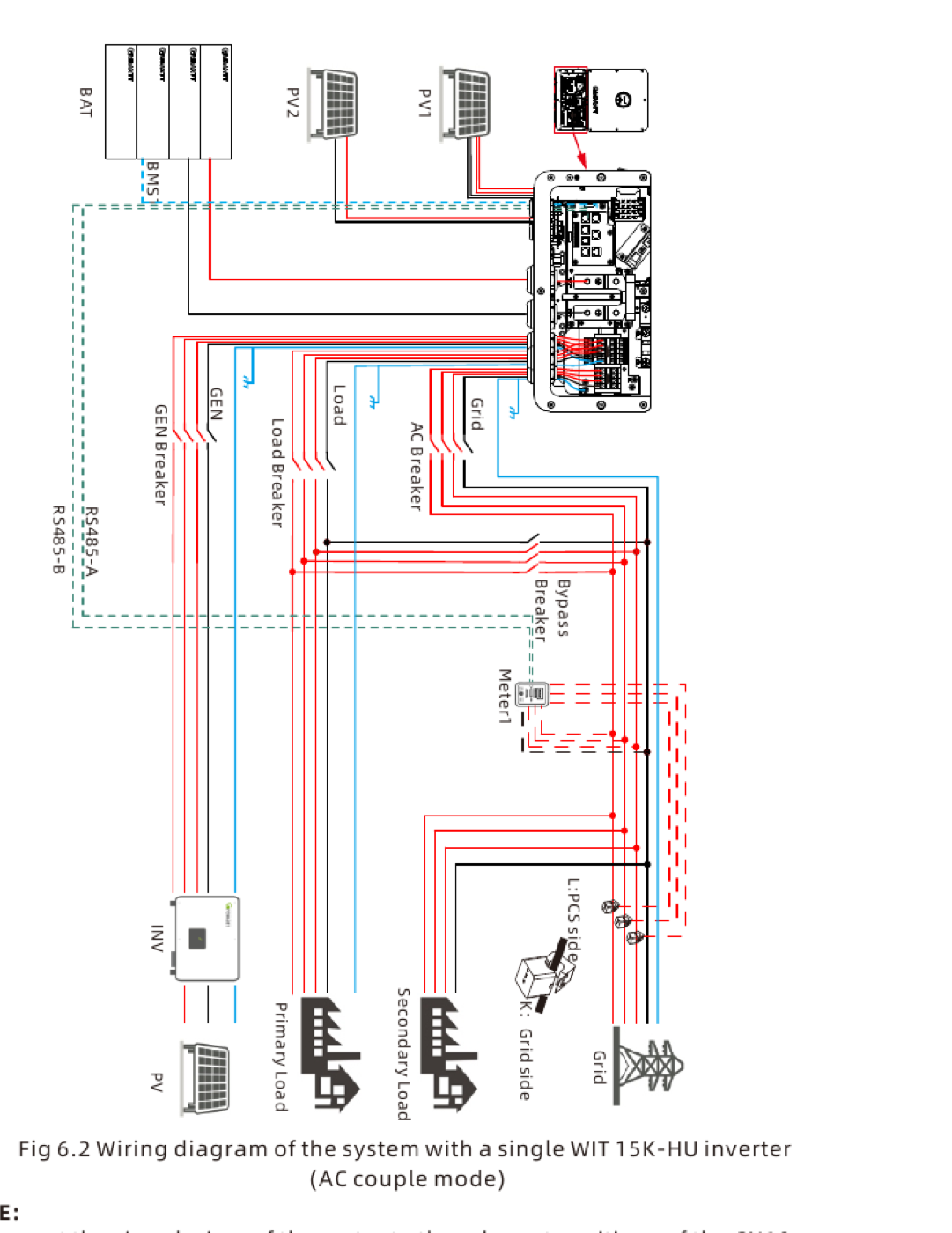
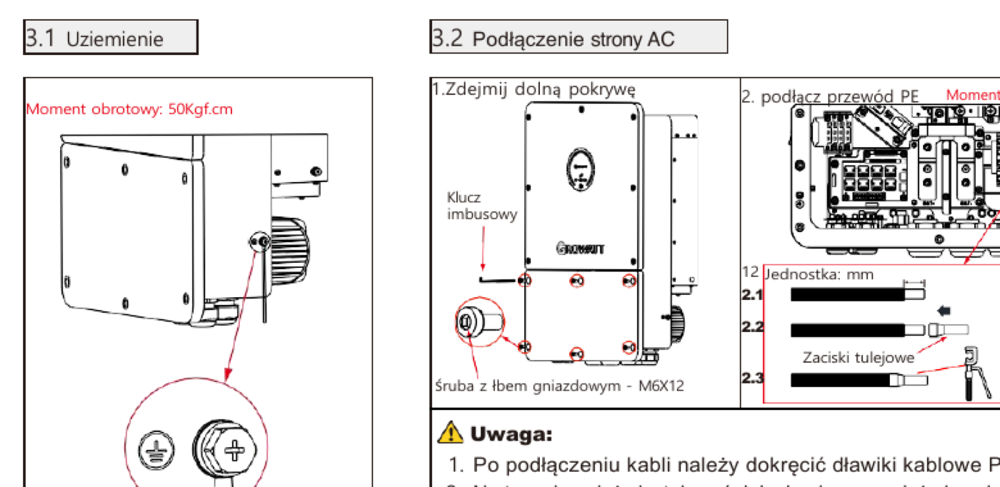
The device supports three-phase, three-wire systems with a protective conductor, and four-wire systems with a neutral and protective conductor. This choice has practical consequences: an emergency power supply section with single-phase loads requires a neutral conductor, so a 3P4W+PE configuration is used in such installations.
| Parameter | Value |
|---|---|
| Connection system | 3P3W+PE or 3P4W+PE |
| Rated voltage | 220/230V (LN), 380/400V (LL) |
| Voltage range | -15% to +10% |
| Rated frequency | 50 Hz |
| frequency range | 45-55 Hz and 55-65 Hz |
| Power factor at rated power | over 0,99 |
| Power factor adjustment range | from -1 to +1 |
| Current Harmonic Content (THDi) | less than 3% |
| AC/DC surge protection | type II |
| Security | insulation control, network monitoring, islanding protection, leakage current monitoring |
The operating range at a frequency of 45-55 Hz and 55-65 Hz does not mean that the inverter will operate in such a wide band in the Polish grid - specific trigger thresholds result from the settings selected in the device configuration.
Security settings and network code selection
Connecting the inverter WIT Connecting to the grid begins with configuration. The device menu contains a separate item dedicated to the grid code, where parameters related to the power factor and the frequency-to-power characteristic are checked. These settings must meet the requirements of the operator whose network the installation is connected to.
In practice, this means three groups of settings. The first are voltage and frequency thresholds along with their response times. The second is the behavior during frequency changes, including the response to the rate of frequency change – the inverter signals exceeding this parameter with the Error 309 code. The third group concerns reactive power control.
Connecting the inverter WIT Connecting the system to the grid without checking the settings usually results in one of two scenarios: the installation disconnects at every minor disturbance in the grid, or, conversely, fails to respond to conditions it should. Checking these parameters upon acceptance takes just a few minutes and is part of the as-built documentation.
It is a good practice to combine the electrical acceptance and configuration in one visit: first the measurements and the protocol according to inverter installation guide WIT, then grid code settings, export limit, and voltage threshold response test. Connecting the inverter WIT The connection to the network is completed only by a complete set of entries in the documentation: settings, measurement results and certificate numbers.
Reactive power and active power regulation
The inverter achieves a power factor above 0,99 at rated power, and the control range covers the full range from -1 to +1, allowing the device to operate in both inductive and capacitive modes. Operators increasingly require operation with a set power factor or voltage-dependent characteristic, as this helps stabilize the voltage in the low-voltage grid.
Active power can be limited by a percentage through the device's system configuration. This feature is useful when connection conditions require a power output lower than the inverter's rated power, and replacing the device with a smaller one is not economically viable.
The device also has a binary input for external control. After enabling this function and applying a signal, the inverter sets the active power and power factor according to the corresponding signal instruction. The manufacturer notes that only one signal can be applied at a time, and the port is shared with the remote power control system.
Export limitation when connecting an inverter WIT to the network
Connecting the inverter WIT to the grid can be performed without feeding energy into the grid. The export limitation function allows the installation to operate in this manner. Once enabled, neither the energy from the modules nor the energy from the batteries is fed into the grid – the inverter output powers only the loads connected upstream of the external meter's measuring point.
A meter is required for this function to work. The meter detects energy flow towards the grid and regulates the generated power to match the current consumption of the loads and the battery charging power. Without this measurement, the inverter has no information about the flow direction, and the function will not work.
The manufacturer points out an installation detail that can cause problems: the arrow on the meter or external current transformers must point toward the inverter. Reversing the current transformers causes the device to interpret consumption as energy output and operate in the opposite direction, signaling a reverse meter connection warning.
The configuration also includes single-phase export limitation, useful for installations with a large share of single-phase loads, where the balance on individual phases differs significantly.
Counter and operating modes depending on the measurement
Load First mode, which prioritizes powering loads from modules and batteries, requires a meter or three current transformers. This mode also sets a power flow threshold: once the load power exceeds a preset value, measured by an external meter, the inverter reduces charging power and increases the share of energy directed to the loads.
This mechanism is sometimes used to limit grid consumption during peak periods when the connection has limited contractual capacity. With a properly selected threshold, the installation automatically reduces storage charging during periods when the home draws high energy.
Connecting the inverter WIT to the grid in an installation with a storage facility almost always involves installing a metering system. It is worth considering this in the quote and switchboard design, as the meter requires space on the busbar and a communication cable to the inverter. The same meter later supports tariff-controlled modes - their configuration is described in the article about mode Growatt Smart Scheduling.
Power limitation at high grid voltage
A common complaint in rural installations and at the end of the line is a drop in production on sunny days. The inverter then limits power as the grid voltage approaches the upper permissible threshold. This behavior is normal and protects the installation and the loads from further voltage increases.
The diagnosis is as follows:
- Measure the voltage at the inverter AC terminals during peak production hours.
- Compare this with the voltage at the main switchboard – the difference shows the drop in the power cable.
- Check the cross-section and length of the AC cable between the inverter and the distribution board.
- Verify the voltage threshold settings in the device configuration.
- If the voltage in the main switchboard is already high, the cause lies with the network and the matter is referred to the operator.
Increasing the cross-section of the AC cable can be the cheapest and most effective solution because it reduces the voltage drop between the switchboard and the inverter and postpones the moment of power reduction.
Before reporting the issue to the operator, gather several days of data: voltage graphs from monitoring, hours of downtime, and measured values from the switchboard. The operator will treat a report supported by measurements differently than a general complaint about a production drop, and this will also help you rule out a wire that's too thin on the installation side.
Meter, transformers and surge protection
Connecting the inverter WIT Connecting to the grid in a warehouse installation requires measurement at the connection point. The manufacturer allows two solutions: a meter communicating with the inverter via RS485 or three external current transformers. The choice affects the installation—the meter takes up space on the rail in the distribution board and requires a communication cable, while the current transformers are mounted on the phase conductors without cutting the circuit.
Regardless of the variant, the same principle applies: the measuring element is installed at the point through which all energy exchanged with the grid flows, i.e., after the main protection, before distribution to the circuits. Installing it after some of the loads gives the inverter an incomplete picture of the balance and disrupts both the load priority mode and the export limitation.
On the AC side, the inverter has built-in Type II surge protection, as well as insulation resistance monitoring, leakage current monitoring, and anti-islanding protection. However, this built-in protection does not replace surge arresters in the distribution board—when installed on a building with lightning protection, the coordination of protection levels must be designed separately, along with grounding.
It's worth collecting connection documentation before visiting the facility. A certificate of conformity for Poland, a declaration of conformity, and a catalog card with network parameters are all required by the operator. We maintain all three documents on our websites, in versions corresponding to the models we sell.
From the installer's practice
Check the transformer orientation at every load. Reverse-mounted transformers are the most common error in export-restricted installations. The test involves comparing the power reading in the app with the actual consumption in the home with the large load turned on.
Determine operator requirements before installation, not after. Connection conditions may impose limits on power fed into the grid or specific settings. Changing the configuration after commissioning means another trip and another notification.
In practice, we often encounter installations in which the connection of an inverter WIT The connection to the grid was made correctly, but the meter was omitted. The customer ordered the energy storage unit for self-consumption, but without metering, the inverter does not prioritize the load and behaves differently than indicated in the offer.
Record the settings in your documentation. The grid code, protection thresholds, set power factor, and export limit should be included in the protocol. This information can save hours when changing building owners or requesting service.
Certificates and documents to be reported to the operator
When connecting, the operator asks for documents confirming the device's compliance with network requirements. A complete set for the series WIT we have:
- Certificate of Conformity for Poland — the basic document for reporting.
- EN 50549 certificate — connection standard for generating installations.
- IEC 62109 certificate — safety of converter devices.
- User manual — Grid code settings and export restriction configuration.
Download the documents before your site visit and attach them to your installation file. Complete documentation is often the difference between timely connection and a request to supplement the application.
FAQ
Does the inverter require a meter?
Yes, if you want to use load priority mode or limit export to the grid. An alternative to the meter is three external current transformers.
What system should I choose when connecting an inverter? WIT to the network?
The inverter supports 3P3W+PE and 3P4W+PE. For installations with an emergency section powering single-phase loads, a neutral wire is required, i.e., a four-wire system.
Why does the inverter limit power on a sunny day?
Most often, this is due to high mains voltage. The device reduces power to prevent further voltage increases. Check the voltage drop on the AC line and compare the values in the main distribution board.
Where can I find the documents needed to report to the operator?
Certificates of conformity and declarations for individual models of the series WIT are available in manufacturer's download center, together with instructions containing connection parameters.
Checklist before pickup
- Plan to connect the inverter WIT to the mains: confirm the layout, cross-section and protection of the AC cable.
- Set the network code and security settings according to your operator's requirements.
- Install the meter or transformers and check the direction of the arrow relative to the inverter.
- Configure export restriction if required by the connection conditions.
- Set active power limitation if the device power exceeds the permissible limit.
- Measure the voltage during peak production hours and record the result in the report.
- Include model certificates and a record of all settings in your documentation.
Series inverters WIT are available in versions from 4 kW do 15 kW in this family, and the full list of models is kept in 3-phase hybrid inverters departmentIn case of unusual connection conditions, the set PVGroup.pl will help you choose a model and determine the required settings.