The most common cause of inverter damage after a storm in a C&I installation is not a direct lightning strike, but a poorly constructed lightning protection of PV installations, i.e., incorrect connection of the inverter's PE protective grounding to the building's lightning protection system. When the PV system's lightning protection and PE grounding share a common conductor or are connected too closely, lightning current enters the inverter enclosure as the lowest impedance path and destroys the electronics on the DC or AC side—often bypassing even surge arresters. The correct rule is simple: the lightning protection and PE grounding of the inverter should be run separately to a common ground point, but using different conductors, and the air terminals should be kept at a safe distance from the equipment. In this article, we show how to do this on a commercial roof, with specific cross-sections and material distances. Growatt.
Does lightning protection for a PV installation on a C&I roof require a separate lightning protection system?
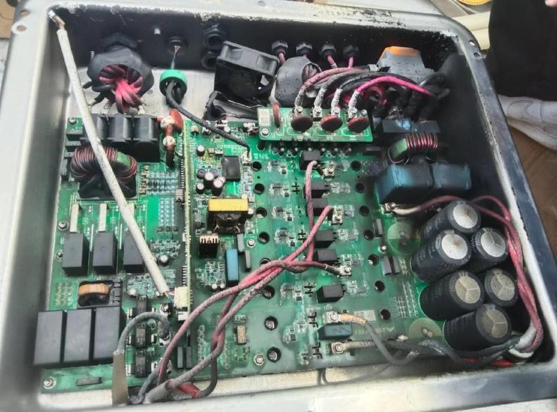
In most cases, no. Lightning protection for a PV installation on the roof of a commercial or industrial building can utilize the facility's existing lightning protection system, provided it exists and is operational. This shortens installation time and reduces costs because it utilizes infrastructure already built in at the construction stage—in reinforced concrete structures, air terminals and the grounding grid are often embedded in the concrete frame.
The approach to steel roofs is similar to that of reinforced concrete roofs. The selection of air terminals, downconductors, grounding electrodes, and connecting materials is based on the same principles. However, an important distinction must be kept in mind from the outset of the project: lightning protection for PV installations is not the same as protective grounding for electrical equipment . Confusing these two systems is the source of most post-storm failures.
Lightning protection for PV installations: selection of materials and grounding
Materials must withstand lightning current and years of roof corrosion. Below, we've gathered parameters from the manufacturer's materials that underlie lightning protection for PV installations—useful for cost estimation and selection on site.
| Element | Material and minimum dimensions |
|---|---|
| Vertical air terminal (rod) | Round steel, diameter 12–16 mm |
| Horizontal air terminals (tape/wire) | Round steel, min. 8 mm thick, or flat steel, min. 4 mm thick |
| Drain pipe | Hot-dip galvanized steel, round min. 8 mm or flat min. 4 mm; for higher requirements, double-layer insulated copper wire 35 mm² |
| Tubular earth electrode | Hot-dip galvanized steel pipe, diameter 50 mm, wall thickness min. 3,5 mm |
| Angle grounding rod | Angle 50×50×5 mm, min. length 2,5 m |
| Flat bar grounding rod | Flat bar 40×4 mm, length 2,5–4 m |
| Depth of flat bar placement | Min. 0,5 m horizontally |
| Depth of the angle grounding rod | Min. 2,5 m vertically |
| Module equipotential bonding | Yellow-green wire 4 mm² |
Every welded joint must be protected against corrosion. On a roof, where contact with water and salt is a daily occurrence, an unplastered weld loses electrical continuity after two seasons, and the PV installation's lightning protection fails precisely when it's most needed.
The module equipotential bonding that is often forgotten
Manufacturers coat aluminum module frames and galvanized or aluminum alloy structures. This means that clamping alone doesn't ensure proper grounding—the coating insulates the contact. Effective module grounding is achieved only when the grounding hole in the module is actually connected to the supporting structure. In practice, this is how lightning protection for PV installations works at the individual module level: a 4 mm² yellow-green wire routed to the equipotential bonding point.
Connections between structural elements must also have durable electrical continuity. Round steel of at least 8 mm or flat steel of at least 4 mm is used, and joining methods include copper-zinc welding, spot welding, edge folding, overlapping, or bolting. Experience has shown that welding is the most durable, but each weld requires subsequent finishing and corrosion protection.
Surge arrester installation zones and safety distance S
Air terminals and downconductors, which largely determine the lightning protection of PV installations, must maintain a safety distance S from panels, inverters, cables, and distribution boards. For a typical five-story building roof with a height of approximately 15 meters, the recommended value of S is approximately 2,5 meters. This value can be simplified and scaled inversely to the building's height—the taller the structure, the smaller the required distance.
The arrangement of surge arresters depends on whether the distance S is maintained:
- When S is preserved: overvoltage modules are installed in positions ①, ② and ③ of the system.
- When S is not preserved: in addition to positions ①, ② and ③, an overvoltage module is also added in position ④.
In practice, this means that on narrow roofs, where the air terminal and the inverter are less than 2,5 meters apart, an additional level of surge protection must be added. Ignoring this is one of the most common reasons why lightning protection fails in PV installations and the inverter fails despite the presence of an SPD.
SPD type I and type II on DC and AC side
The inverter has internal surge arresters on both the DC and AC sides, grounded to the device's ground terminal. This is a good basis, but does not eliminate the need for protection at the installation level. On roofs exposed to direct lightning strikes, SPD type I (test class I) is used where some lightning current can flow, and SPD type II is used on further sections to protect against induced surges. However, SPDs alone are not sufficient if the PV installation's lightning protection is based on an incorrect grounding system—we discuss this below.
Inverter Grounding: Functional (PE) and Protective Housings
The inverter is the electrical heart of a PV power plant, so lightning protection for a PV installation requires more robust grounding than other components. We distinguish between two systems.
Functional grounding (PE terminal) connects to the PE busbar in the switchboard and then grounded via the distribution system. The inverter's PE terminal serves as a functional ground and cooperates with the ground fault detection on the PV side. This ensures that the protection will trip in time in the event of a ground fault. The DC side is particularly susceptible to lightning-induced overvoltages – these transient voltages can damage the DC system insulation and lead to grounding of the positive or negative pole of the string, preventing synprotection from the network and turns off production.
The protective ground (PE) is a grounding point outside the inverter enclosure. It serves as a supplementary ground to protect both the device and operator safety.
Why an Inverter Fails After a Storm: The Failure Mechanism
The crux of the problem lies in what happens when the lightning protection ground and the inverter's PE are shorted or connected too closely. Without a lightning strike, both systems appear to function properly and the inverter operates safely. The problem only becomes apparent during a storm.
The DC and AC arresters inside the inverter are grounded to the chassis ground terminal, which is then connected via a cable tie to a short air terminal or the module support structure. This creates an equipotential bond between the inverter ground point and the external lightning protection system. During a lightning strike, this creates several hazards:
- When lightning current enters the ground through the lightning protection system, the inverter's chassis ground point becomes the entry path for this current. The potential at the ground terminal increases dramatically—by up to tens of kilovolts—and exceeds the voltage on the AC and DC lines. This creates a backfeed phenomenon.
- The inverter circuit is grounded at multiple points and contains capacitors X and Y that couple transient surges. This allows reverse surges to enter the DC/DC or DC/AC circuits, often far from the SPD's installation location. The SPD may then fail to operate, and the transient voltage exceeds the inverter's internal circuitry.
- In the event of a direct strike to an air terminal or supporting structure, the surge current takes the shortest path to the inverter along the grounding system—due to the short distance and low impedance. This is the most severe scenario—a catastrophic current overload can lead to component explosions.
- When the grounding resistance of the air terminal is too high, the grounding network formed by the modules, inverters, and lightning protection system creates high-impedance return paths. This creates high reverse voltages that damage the inverter circuitry. The problem is exacerbated in simplified designs with poorly constructed or insufficiently grounded downconductors.
Correct solution: split grounding
The principle resulting directly from the fault analysis is clear: effective lightning protection for a PV installation requires that the lightning protection grounding system and the inverter's PE protective ground remain separate. The correct connection method is as follows:
- The PE protective conductor of the inverter is connected independently to a dedicated grounding electrode.
- The PE down conductor and the lightning protection down conductor should be routed as far apart as possible – preferably more than 10 meters.
- We connect both systems only at a common grounding point, but via separate wires - never a common wire.
This means that when lightning current enters the ground through the lightning protection system, it dissipates quickly into the surrounding ground, reducing the risk of current returning to the inverter via the PE line. Even if some current does return due to unbalanced impedance, it will be small enough not to damage the device.
From the installer's practice
- Do not “connect” the inverter’s PE to the nearest structure. This is the most common mistake on construction sites—the installer sees a metal frame and connects a PE wire to it because "it's grounded." It works without a lightning strike. After the first major storm, the inverter needs replacing, and the farm is down.
- Check the grounding resistance of the air terminal, do not install it. High ground resistance in weak soil creates high-impedance return paths. Measuring the ground resistance after installation takes several minutes, and missing the test costs the inverter money.
- Treat coatings as an insulator. The pressure clamp on the anodized frame and coated construction does not provide reliable grounding. Run a 4 mm² yellow-green wire to the module's grounding hole—otherwise, potential equalization exists only on paper.
- Secure each weld. A weld without anti-corrosion treatment is a ticking time bomb - it loses its continuity after two seasons and the entire lightning protection chain ceases to function invisibly.
C&I inverters with built-in surge protection
Series inverters Growatt WIT-HU and MOD-HU have internal surge arresters on both the DC and AC sides, grounded to the chassis ground terminal. This is a good hardware foundation, but—as the failure mechanism analysis shows—a built-in SPD is no substitute for properly separated grounding. The hardware and design must work together.
It is worth checking out the model on offer Growatt WIT25K-HU for commercial installations and three-phase Growatt MOD 15KTL3-HUFor full specifications, grounding requirements, and connection diagrams, please refer to the catalog sheets and manuals in download center GrowattAll devices come with a European service warranty.
FAQ
Does lightning protection for a PV installation on a C&I roof require a separate lightning protection system?
Typically not. The building's existing lightning protection system can be used, provided it is functional. Provided a safety distance S is maintained between the air terminals and the PV components, and the lightning protection grounding is separated from the inverter's PE.
What should be the distance between the PE conductor and the lightning protection down conductor?
According to the materials Growatt Both down conductors should be run as far apart as possible, preferably more than 10 meters. They should be connected only at a common grounding point, but always with separate conductors, never a single shared conductor.
Why does an inverter with a built-in SPD still get damaged after a storm?
Because with incorrect, common, or too close grounding, reverse voltage surges enter the inverter via the PE line, near the DC/DC or DC/AC circuits, far from the SPD installation location. The transient voltage then exceeds the internal circuitry's capacity despite the presence of a surge arrester.
What wire cross-section should be used to ground PV modules?
A 4 mm² yellow-green wire is used to equipotentially connect the modules, routed to the module's grounding hole. Simply clamping the coated frame does not ensure proper grounding.
Implementation Checklist: Lightning Protection for PV Installations in C&I Projects
- Check whether the building has a functioning lightning protection system and whether it can be used.
- Keep a safety distance S (approx. 2,5 m for a building ~15 m) between the air terminals and the PV elements; if S is missing, add an SPD in position ④.
- Run the lightning protection grounding and the inverter's PE in separate wires, and connect them only at a common ground point.
- Keep downpipe spacing above 10 m.
- Make the PE grounding of the inverter as a dedicated, independent one.
- Make equipotential connections of the modules with a 4 mm² wire to the grounding hole, do not rely on the clamp pressure.
- Protect every weld and connection against corrosion.
- Measure the ground resistance after installation and document the result.
Start selecting a C&I inverter with the right surge protection equipment with our range of inverters for commercial installations – and the rest of the safety is ensured by properly separated grounding.