
Feature dry contact in the inverter off-grid Growatt This is a relay controlled internally by the inverter, which switches three contacts (NC, C, NO) depending on the device's operating status and battery charge level. Dry contacts are most often used to automatically start a generator when the battery voltage is low and for remote signaling of operating status. The relay is rated at 3 A / 250 V AC, so it controls the signal, not the load's power. In this article, we explain the full logic of contact switching, show the connection diagram, and provide an example of parameter configuration. SPF6000ES PLUS - manufacturer documentation is available only in English and incorrect interpretation of NC/NO logic is one of the most common problems when commissioning off-grid installations.
What is the purpose of dry contact in an inverter? off-grid
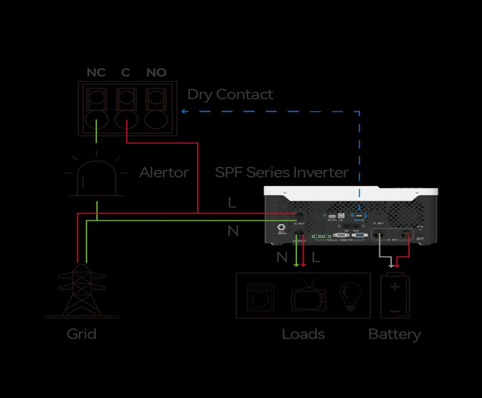
Dry contact transmits a control signal to external devices depending on the current status of the inverter. In installations off-grid Growatt series SPF The most important application is to automatically start the generator when the battery discharges to a preset threshold. It is also used for remote alarms (signaling that the inverter has stopped generating voltage) and to control the low battery indicator light.
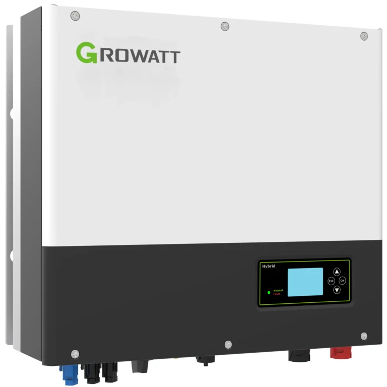
Inverters off-grid They often operate in locations remote from the grid or where the grid is unstable. In such conditions, the generator acts as a backup power source and must start without the presence of personnel. A good understanding of dry contact logic directly translates into the stability of the entire system. Growatt SPF6000ES PLUS provides a dry contact port as standard equipment.
Three contacts: NC, C, NO - what do they mean in practice?
Port dry contact in SPFThe 6000ES PLUS has three pins that the inverter switches with an internal relay. This is a classic changeover contact configuration:
- NC (Normally Closed) — normally closed contact; in the relay idle state connected to contact C.
- C (Common) — common contact, reference point for both others.
- NO (Normally Open) — normally open contact; connects to C only after the relay is activated.
The relay switches between two states. At rest, the NC-C pair is closed and the NO-C pair is open. When the inverter energizes it, the situation reverses: NC-C disconnects and NO-C closes. The entire control logic boils down to when the inverter energizes the relay and which contact is connected to the external device.
Contact switching logic depending on the inverter status
This is the most important part, where installers most often make mistakes. The behavior of the dry contacts depends on the inverter's operating state and the output priority setting (parameter 01). The table below summarizes all the cases described in the documentation. Growatt.
| Inverter operating status | Condition | NC-C | NIGHT |
|---|---|---|---|
| Inverter off (no voltage at output) | compact | obtuse | |
| Operation in bypass mode | compact | obtuse | |
| Converter mode, Utility priority (par. 01) | Battery voltage/SOC below alarm threshold | obtuse | compact |
| Converter mode, Utility priority (par. 01) | Voltage/SOC above the value in par. 13 or battery in trickle charge | compact | obtuse |
| Converter mode, Solar / SBU priority (par. 01) | Battery voltage/SOC below value in par. 12 | obtuse | compact |
| Converter mode, Solar / SBU priority (par. 01) | Voltage/SOC above the value in par. 13 or battery in trickle charge | compact | obtuse |
This table provides a simple rule of thumb: the relay is energized (NO-C contact closed) when the battery is discharged below a certain threshold. In the normal state, with a charged battery or with the inverter turned off, the NC-C pair is active. This answers the most common question from installers—why the generator starts with a full battery? Typically, the cause is the control connected to the wrong contact.
Why the threshold depends on the output priority
Note the difference between utility and solar/SBU priority. With utility priority, the trip threshold refers to the low battery voltage alarm point. With solar or SBU priority, the inverter uses the value stored in parameter 12. In both cases, the contact returns to the rest state when the value in parameter 13 is exceeded or when the battery enters float charging mode. These are two different thresholds – a lower (start) and an upper (stop) – which helps avoid continuous switching at the voltage limit.
Connection diagram - three typical scenarios
The choice of dry contact depends on what is to be done and the inverter's status. Below are three scenarios directly from the manufacturer's documentation.
1. Remote operating status alarm
We want to warn the user that the inverter has stopped generating voltage. We connect the alarm signal's power supply to the NC-C pair. When the inverter is operating normally and energizing the relay during discharge, the NC-C contact is open. When the inverter shuts down (no output), the NC-C contact closes and the alarm sounds. In practice: alarm sounds = the inverter has no output; silence = the inverter is operating.
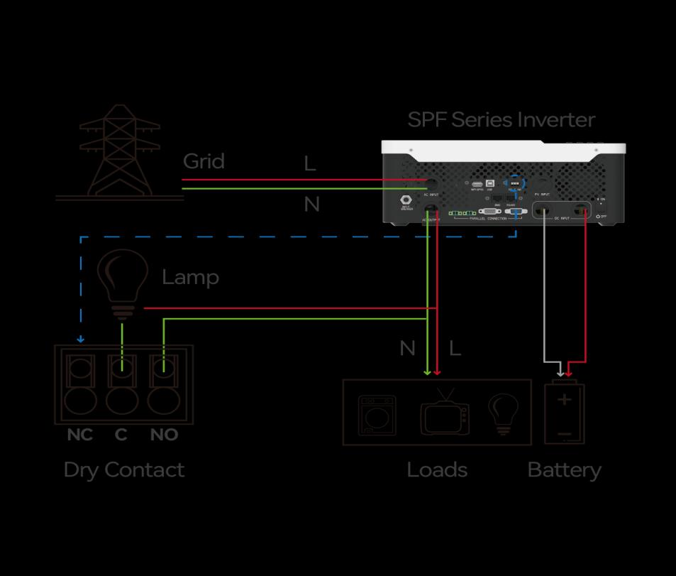
2. Low battery indicator light
To turn on the lamp when the battery voltage is low, we connect the lamp's power supply to the NO-C pair . When the battery voltage drops below the threshold, the relay energizes, the NO-C closes, and the lamp lights. Once the batteries have charged to the required level, the relay returns to rest and the lamp automatically turns off.
3. Automatic generator start
This is the most common application in off-grid installations. The generator start control input is connected to the NO-C pair . When the battery discharges below the threshold, the NO-C contact closes, triggering the engine start. The generator then supplies energy to charge the battery and power the loads. Once the batteries are charged, the relay returns to rest, the contact opens, and the generator can be stopped.
Critical requirement: The generator must have its own dry-contact remote start feature. If the generator does not support a dry-contact input, the inverter contact alone will not do anything—an ATS module or generator controller with such an input is required.
Step-by-step parameter configuration
The dry contact logic itself works automatically, but the voltage thresholds and output priority must be set correctly, otherwise the relay will switch at the wrong times. Configuration sequence:
- Set output priority (parameter 01). Select Utility, Solar (SOL), or SBU based on your installation. This determines which threshold (alarm or parameter 12) triggers the contact.
- Set the lower threshold (parameter 12). In Solar/SBU mode, this is the voltage or SOC at which the NO-C contact is to close, i.e. the generator start level.
- Set the upper threshold (parameter 13). This is the value at which the contact returns to rest and the generator can be stopped. Set it with a reasonable margin above the lower threshold to avoid frequent cycling.
- Check the physical connection. Make sure that the generator control is set to NO-C and any operating status alarm is set to NC-C.
- Test operation before commissioning the installation. Force a discharge or temporarily lower the threshold to verify that the relay actually switches when expected.
The exact parameter designations and default values for a specific firmware version can be found in the device manual - you can download it from download center GrowattWe recommend downloading the version that exactly matches the model and revision, as the parameter numbering in different series SPF can vary.
Common errors in interpreting dry contact logic
- Confusing NC with NO. The most common mistake. The installer assumes that "generator start" is a normally open contact in the common sense, and confuses the switching direction. Remember: when the battery is discharged, the NO-C pair is active.
- Connecting power instead of signal. The relay is rated at 3A/250VAC. This is a signal contact. It must not be used to directly power a high-power contactor coil or starter motor – an intermediate relay or generator control input is required.
- No dry start function in the unit. It sometimes happens that the installer connects a contact to the generator without a remote start input and then does not understand why the generator does not start.
- Too close to the par 12 and par 13 thresholds. If the difference between start and stop is small, the generator starts and stops in short cycles, which shortens its life.
- Bypass mode not included. In bypass mode and when the inverter is off, the dry contacts are in the idle state (NC-C closed). This must be accounted for in the alarm logic to avoid generating false signals during mode transitions.
From the installer's practice
- Always test your logic before committing your installation. From experience, the quickest way to check operation is to temporarily lower the threshold in parameter 12 so that the relay operates at the current battery voltage. After testing, restore the target value.
- Use an intermediate relay. Even if the generator has a dry start input, in many cases a small 12 or 24V intermediate relay that separates the inverter circuits from the engine control and protects the 3A contact is better.
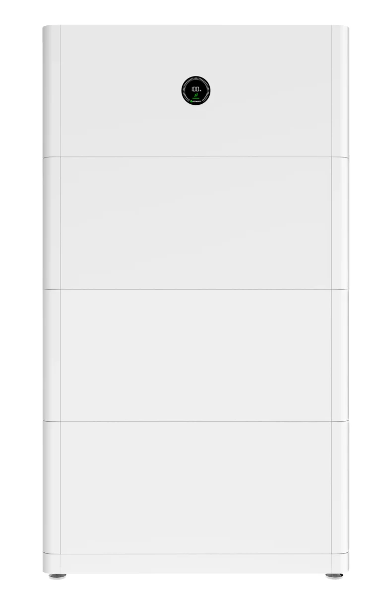
- Match the thresholds to the battery capacity. With a set like this SPF6000ES with batteries AXE-L work on SOC with BMS, not on the voltage, because the LiFePO4 curve is flat and voltage control can be unreliable in the middle range.
- Describe the contacts on the as-built diagram. Another technician doesn't know your assumptions. One "NO-C = generator start" signature saves hours of diagnostics.
FAQ
Can I directly connect a large receiver via dry contact?
No. The internal relay is rated at 3 A / 250 V AC and is used to transmit the control signal. To switch higher power levels, use an intermediate relay or contactor triggered by a dry contact.
Which pin should I connect the remote start of the generator to?
To the NO-C pair. The contact closes when the battery discharges below the set threshold, triggering the generator start. Once the battery is charged above the value set in parameter 13 or after entering float mode, the contact returns to rest.
Why does the generator start with a charged battery?
This is most often the result of connecting the control to the NC-C contact instead of the NO-C contact, or incorrectly set output priority. Check parameter 01 and whether the unit control is being sent to the correct pair of contacts.
What is the difference in logic for Utility and Solar/SBU priority?
With Utility priority, the starting point is the low battery voltage alarm. With Solar or SBU priority, the inverter uses the threshold stored in parameter 12. The upper return threshold (parameter 13 or float state) is common to both cases.
Practical startup checklist
- Set the output priority (parameter 01) according to the installation assumptions.
- Set the lower start threshold (parameter 12) and the upper stop threshold (parameter 13) with a margin.
- Connect the generator start to the NO-C pair, the operating status alarm to NC-C.
- Use an interposing relay to avoid overloading the 3A contact.
- Confirm the generator has a remote start (dry start) input.
- Test switching at a lower threshold, then restore target values.
- Describe the joints on the as-built documentation.
A properly configured dry contact system transforms an off-grid system into a maintenance-free system—the generator starts automatically, alarms work, and the battery doesn't drop below a safe level. You can find inverters with this feature and ready-made battery kits in the category inverters off-grid w PVGroup.pl, where each device is covered by a European service warranty.
When starting the generator automatically, it is worth specifying that NO-C in Growatt It provides a maintained contact, and many motorhome generator controllers expect a START/STOP impulse. In such cases, I add a time relay or autostart module instead of connecting the dry contact directly. And I treat 3A solely as a signal, never to power the starter solenoid.